In use at Point of Ayre Lighthouse 1890 - 1991 Diagrams and drawings not to scale
Lifting the brake/clutch lever would allow the dog clutch to engage and the last movement of the lever lifted a brake pad applied to the worm drive spindle and the lens would turn When putting the light out in the morning,the reverse happened,brake applied,dog clutch disengaged which allowed the lens to be turned manually for cleaning,etc.
 Clockwork Drive mechanism
Description of clockwork mechanism in three parts
| |
| Drive
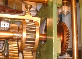
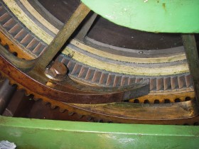
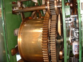 Cable drum ,rewind and primary gears
|
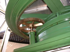
Showing clockwork drive to turn lens Cable wrapped around drum with a 90 pound (42 Kilo) weight turned cable drum and primary gears when brake released.
Power transferred via spur gear to bevel gear
Lifting the brake/clutch lever would allow the dog clutch to engage and the last movement of the lever lifted a brake pad applied to the worm drive spindle and the lens would turn When putting the light out in the morning,the reverse happened,brake applied,dog clutch disengaged which allowed the lens to be turned manually for cleaning,etc.
|
 Dog Clutch 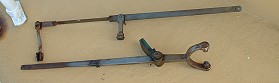 Brake/Clutch lever and Brake pad |
 Final gear drive to lens |
|
| |
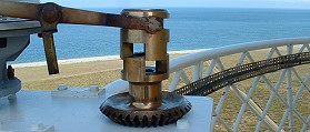
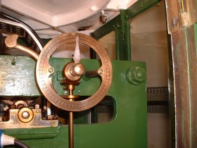
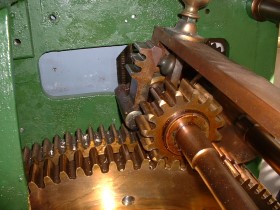
Speed Control
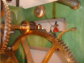 Spur gear drive to worm gear Little brass flap on the right hand side operated a bell striker,sounded a ding ding ding as lens turned |
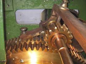
Another small spur gear from primary gear,on left side drives clock and through large gear on right via spur gear to worm drive Final worm drive spindle turns an air rotor with adjustable blades which gives a rough speed control Final speed control achieved with adding or removing weights from main weight. You set the clock after rewinding,checked on next wind and adjusted as required.
|
 Worm/Air rotor drive |
 Clock,bell (Removed on automation to allow room for motor mount) used to strike every hour |
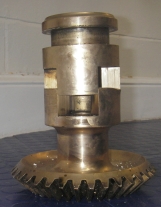
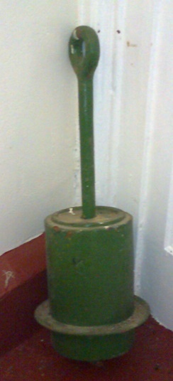 Weight 90 lbs (42 Kilo) | 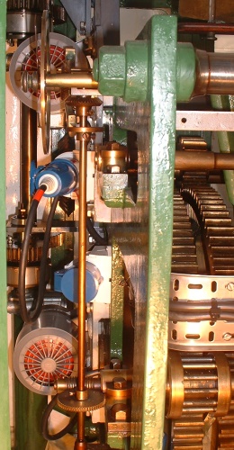 Clock Drive |
Bevel Gear | 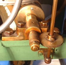
Worm Gear |
|
Clock Drive Spur gear from maindrive gear,worm gear to spindle,bevel gear to clock pointer
| |
|
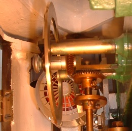
Rewind One of the "Crimes" for a lightkeeper to commit was to allow the light to become stationary or run at the wrong speed.Showing a false character? So a way had to be found to allow the lens to contnue rotating as the weight was rewound.
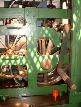 Winding handle on swinging frame | |
|
Rewind Mechanism
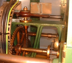
The gear wheel turning the rewind gear on the cable drum was mounted on a swinging frame which could be locked to the primary gear,as the weight was rewound the primary gear with swinging frame continued to rotate and turn the lens.
One thing was to note how far the swinging frame had rotated,if allowed to rotate too far it would lock the mechanism against the main frame and everything would stop,so it was rewind so far then release the gear lock, reset the swinging frame and gear lock and carry on winding
|
 _____
_____
During rewind operation as cable drum is rewound the ratchet lever on primary gear goes Click Click Click and gears turn in opposite direction.
|
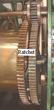 Ratchet teeth cut into side of cable drum Two ratchet levers Ratchet lever pivots mounted 180 degrees apart on primary gear,spring tension applied by flat steel strip under tension In normal operation ratchet lever engages ratchet teeth on cable drum and transfers drive to primary drive gear Ratchet operates when cable drum is rewound,primary gear continues to revolve in normal direction. |
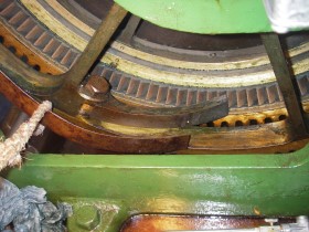 Ratchet lever and pivot with spring tension applied ---- Showing spring lever strip
 Swinging arm gear lock - free ------------ Swinging arm gear lock - locked
|
 Some lighthouses had the weight dropping in a channel cut into tower wall,which gave more room,especially in towers used for accommodation.
The pulley below cable drum was free to slide on shaft which allowed cable to freely wind on and off drum. |
|
This was the type of lifting jack used when chariot wheels were fitted
|
 In normal operation ratchet lever engages ratchet teeth on cable drum and transfers drive to primary drive gear.
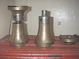 ________
All photographs Copyright Fred Fox.