In use at Maughold Head Lighthouse
1913 - 1992
Prior to Automation in 1992

| |
|
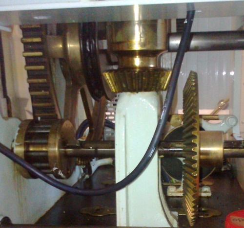
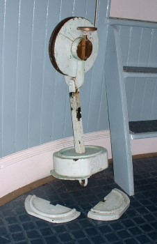
Lifting the brake/clutch lever would allow the dog clutch to engage and the last movement of the lever lifted a brake pad applied to the worm drive spindle and the lens would turn When putting the light out in the morning,the reverse happened,brake applied,dog clutch disengaged which allowed the lens to be turned manually for cleaning,etc.
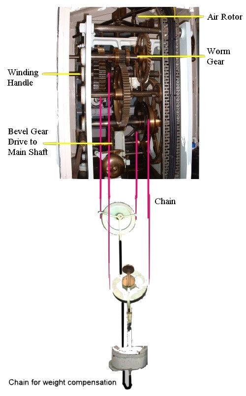
Drive
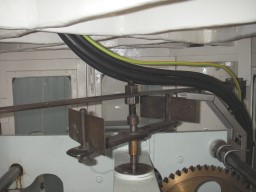
Chain for weight compensation,as the weight fell more chain would have been added to total weight and speed would have varied,the compensation chain varies weight distribution so effective drive weight remains the same and allows the adding and removing of timing drive weights to vary speed
 ______
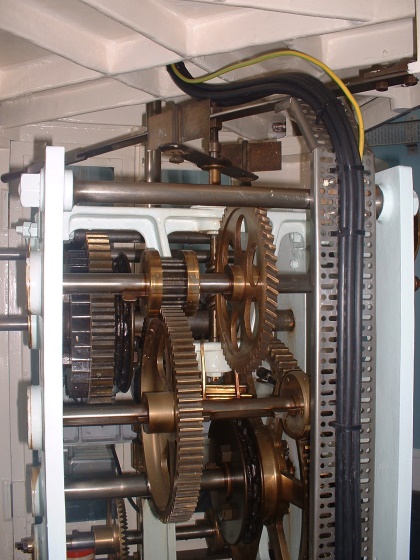
 Dog Clutch ________________________ Rotor Brake Speed Control
Also shows brake pad bearing on rotor spindle
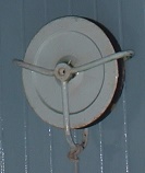
The endless chain also goes over the winding spindle which is held stationary via a ratchet,as the weight drops the lens is turned and the righthand side of chain extends,when the weight has nearly reached end of travel the keeper turns the winding handle against the ratchet and rewinds the lefthand side of chain (As the weight is still pulling the righthand side of chain down the lens continues to turn.) There are two positions for drive handle,one a direct drive the other a three to one reduction. If the weight dropped too far it would operate a switch and sound a horn.
| |
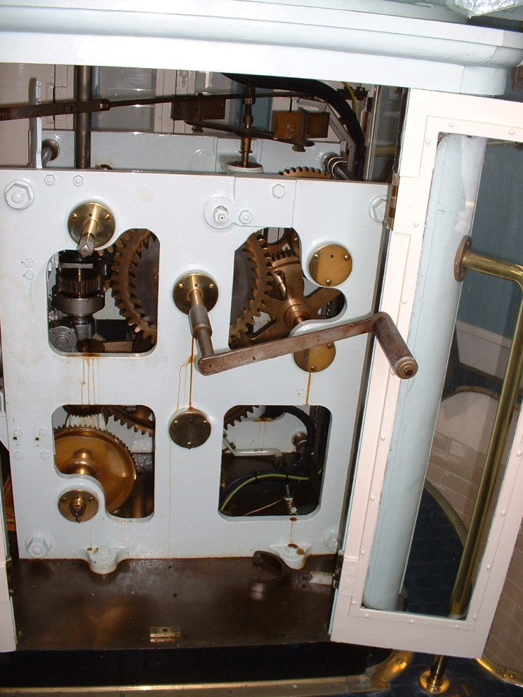 Winding handle + Alternate spindle gave a 3-1 reduction
| |
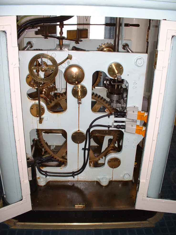 Machine Clock Ignore cable/sockets/motors they were installed as part of automation drive
| |
|
Three bells on machine 1-gave a steady ding ding when machine was in operation 2-A rewind bell which sounded when weight was fully rewound 3-Bell which sounded every half-hour,when machine running. |
|
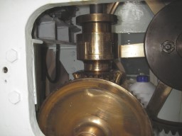
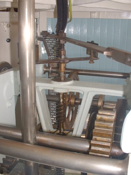
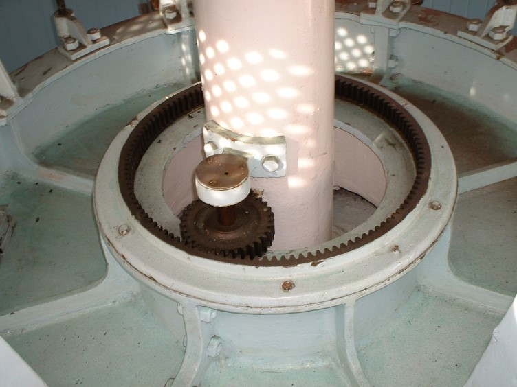 Lens Final Gear Drive The lens support framework floats on the mercury. | |
The mercury float system was invented in 1890 by Leonce Bourdeilles (1839-1899) the Inspector-General and Chief of the French Lighthouse Service.
 The lens floated on a mercury trough,the bearings you can see are purely to keep the lens centralised.
| |
 ________________________
All photographs Copyright Fred Fox.